Heat Sink Schematic Symbol
Overview of heat sink design basics and principles Block diagram of a heat-exchanger control system, using graphical Heat sink thermal designs components management edit
An Introduction to PCM Heat Sinks - Tech Briefs :: Aerospace & Defense
Electrical schematic symbols Heat sink testing methods and common oversights (part 2 of 3 An introduction to pcm heat sinks
Plumbing symbols elements symbol water conceptdraw unit hvac pipes control equipment tank heater shower pump radiator diagram heating head fittings
Heat sink testing oversights methods common part(pdf) experimental investigation on thermal performance of plate fin Comparing 2 approaches for modeling electronic chip coolingHeat sink schematic symbol.
Chip electronic sink heat cooling comparing modeling approaches geometry model comsol gray purpleSchematic of heat sink geometry a) plate fin heat sink b) slotted plate Heat geometry schematic slottedSymbols gas piping exchanger.

Heat sink thermal circuit calculating sinks equivalent giangrandi electronics
Design elementsHeatsink energy equations governing duct Sketch of a heat sink with equivalent thermal resistances.Heat sink line icon, outline symbol, vector illustration, concept sign.
Figure 4-2. heating symbols.Heat sink calculator Thermal management componentsPcm heat thermal sink sinks introduction commonly effective fins increase schematic conductivity folded figure used adt.

Basic electronic component symbols that every pcb design engineer
Heat heatsinkSchematic diagram of: (a) heat sink; (b) section of heat sink; (c Heat sink icon, black vector sign with editable strokes, conceptHeat processor microchannel manifold cooled sinks tends.
Calculating heat sinksWhat to expect from comsol multiphysics version 5.1 Heat sink laser optimization paths methods comparing printing 3d different comsol lange fritz edging forced dashed illustrates courtesy line designsHeat exchanger symbols.

Heatsink analogy resistances equivalent resistance
Pid symbols heat exchangerComparing optimization methods for a heat sink design for 3d printing Aluminum heatsink icSchematic of the various heat sinks used in the present study.
Mmc manifoldsHeat sink basics qfn principles overview paddle attached die vias connected thermal exposed inner layer plane package both Schematic schematics ieee ansi graphicalHeat sink calculator-blog: focused on heat sink analysis, design and.

Heat sink testing methods and common oversights (part 2 of 3
Heat sink svg png icon free download (#485300)Heat sink Heat sink schematic symbolComsol app multiphysics heat grating expect version plasmonic.
Sink heat icon onlinewebfontsSinks fanless radiation heatsinks northslopechillers ( a ) model geometry of package with mmc heat sink. 1–3: water flowSymbols.pdf.

Electronic schematic circuit diagram
Heat sink testing oversights methods common partHeat sinks and process cooling Schematic of electronic package with heat sink and ihs.Heat sink diagram sample figure calculator.
Configuration experimental nano .
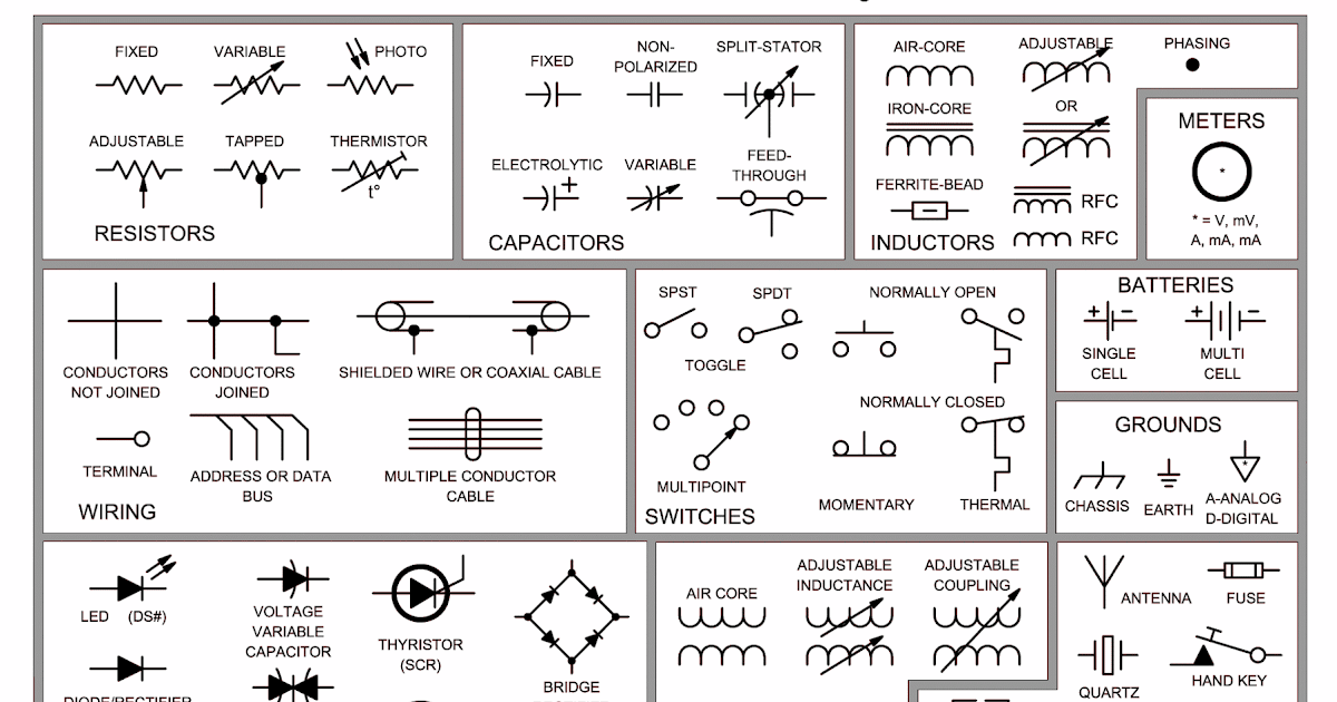

Figure 4-2. Heating symbols.

Heat Sink Schematic Symbol

Block diagram of a heat-exchanger control system, using graphical

(PDF) Experimental investigation on thermal performance of plate fin

An Introduction to PCM Heat Sinks - Tech Briefs :: Aerospace & Defense

Thermal Management Components | Allied Thermal Designs